
Contents
- The components of a photovoltaic system
- Three Typical Photovoltaic Troubleshooting Situations
- 1: Cell / Module / Set
- 2: Charging
- 3: The Investor
Heating, ventilation and air conditioning systems, Renewable energy; with the trend towards energy autonomy and renewable energy sources, we need to know how to troubleshoot photovoltaic systems
Given the energy problems and situation in recent years there has been a major effort to increase the amount of energy obtained from renewable sources. Federal and state government policies call for increased use of solar energy in many areas. Some technician maintaining other equipment in the building may come across solar energy systems. As the concepts and arrangements of these systems are new, it is worth briefly giving an overview of the systems and components.
Photovoltaic systems convert sunlight (photo) into electrical energy (voltaic). Sunlight striking the semiconductor material in individual cells causes electrons to travel through a wire. The electricity generated by photovoltaic systems can be used to power a variety of equipment, from household appliances to commercial production equipment.

There are many variables within a photovoltaic system, but typically a photovoltaic array is installed on a roof facing south, as far as possible. Obstructions are avoided. Bear in mind that less energy is generated in winter than in summer, as the days are shorter. In addition, the maximum energy is generated at noon, more than in the morning or in the evening.
As part of the photovoltaic installation, some installations have a “real-time” computer screen that shows the amount of energy generated by the assembly, the money saved, and the amount of fossil fuels that was avoided. It’s great to know that facilities are increasingly leading the way to energy autonomy and reducing pollutants released into the atmosphere!
The electricity generated by a photovoltaic system can be used immediately within the facility, stored or, in some cases, sold to the public electricity company.
It is normal for facilities that have these systems to expect technicians to know at least the fundamentals of photovoltaic systems. As these systems become more common, we are expected to be able to fix the basic problems.
The components of a photovoltaic system
Photovoltaic systems consist of the following general components:
Individual cells: An individual cell is a small piece of a photovoltaic system. A cell consists of the semiconductor material, a support structure, and a transparent material that allows sunlight to hit the semiconductor material. The cell must be solid, as it is exposed to the elements. The transparent material that covers the cell should also repel stains and dust. Each individual cell only produces a few watts of electricity.
Modules and sets: A module consists of a number of cells connected to each other side by side. The modules can be connected in series or in parallel, as necessary to obtain the desired voltage and current. As each individual cell only produces a small amount of electricity, many of them together are necessary to obtain significant amounts of electricity. As you can imagine, these modules get quite large and are limited by the size of the ceiling dedicated to their use. Assemblies are modules installed together. The individual cells are connected with cables to form these assemblies. The assemblies in turn are wired to a central point.
Concentrators and Combiners: A hub or combiner is a central wiring point for cells and modules. Represents the total energy output of the entire solar array; although the output of each solar cell is small, many amps of current are present at the point where multiple modules are connected. Energy metering and conditioning can also take place in the concentrator. The concentrator is then connected to electrical storage or an inverter. Storage can consist of a large number of batteries.
Investors: photovoltaic system produces DC. The vast majority of loads in a building are AC. An inverter is used to convert the DC generated by the modules into usable AC. The inverter output can also be connected to the local utility, so that surplus energy is returned to the electrical grid and purchased by the utility for use by other users. Measurement and monitoring equipment is also installed at this point.
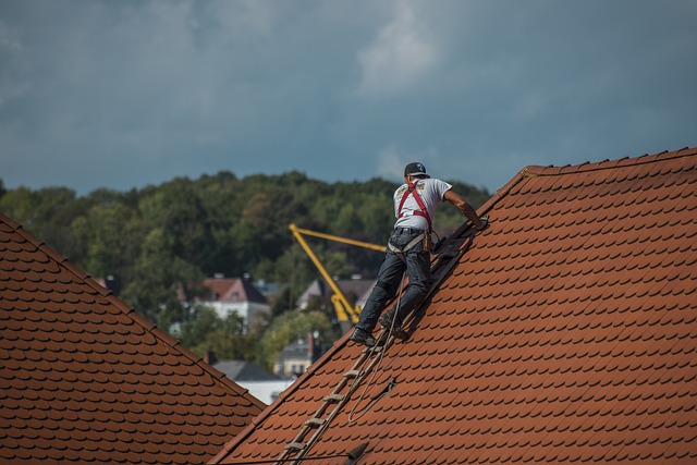
Few things can go wrong with photovoltaic systems, as they consist of very few components. As mentioned above, the main components are the cells, modules, assemblies, hub / combiner, and inverter. The photovoltaic system in a building can supply energy to the HVAC equipment or affect the electrical quality of the building. Which means HVAC technicians need to have basic troubleshooting skills; (After all, you are expected to know how to work on everything on the roof, right?)
Three Typical Photovoltaic Troubleshooting Situations
In the following examples, the troubleshooter takes advantage of the features of the new Fluke 381 Detachable Display True RMS Clamp Meter with iFlex ™. While you can use a voltage-capable, true-rms DC / AC clamp meter to do most of the work, we used the Fluke 381 for its wireless feature (detachable readout and display) and the flexible iFlex ™ current probe. The iFlex ™ probe is absolutely essential for diagnosing problems in photovoltaic systems. As large numbers of cables connect each module and each assembly to the hub box, the junction boxes are filled with individual cables. The iFlex ™ probe makes measuring individual module leads MUCH easier,

1: Cell / Module / Set
As you do with any other troubleshooting request, try to get as much information from the customer as possible. Try to find out when the problem occurred and when the PV system last operated normally. Get as much information as you can, such as printouts, wiring and output diagrams.
A good start is to check the output of the entire system at the measurement system or at the inverter. Before going up to the roof, check and record the input voltage of the inverter and the current level of the array. If the entire PV system is out of service and not producing power, it may be an inverter problem. If the PV system is operating with a reduced power output, the problem may be with one of the assemblies or modules. You will have to follow the wiring from that branch back to the hub. Again, the iFlex ™ probe makes this task easy.
When you get to the ceiling, visually check the entire system for any obvious damage. Also, keep in mind that someone could have accidentally disconnected the cables while servicing another device on the roof. Once you find the module or assembly that is not producing power, check all cables, switches, fuses, and circuit breakers. Replace open fuses and reset breakers and switches. Keep in mind that since the PV system is located on the roof, a lightning strike or power surge could have affected it. Given the presence of a large number of cables, check for broken cables, dirty or loose connections; Replace and clean as necessary. Pay particular attention to the wire nuts that connect the modules to each other.
Hubs can be an excellent site to diagnose your system, as individual cables from the modules are routed there. Each module may have a fuse that must be checked with the 381 meter.
Wiring problems and loose connections can also cause a particular module to produce too low a voltage. Again, all cable connections need to be checked. If the output of a particular module is low, it may be that a section of cells is not working. They can be located using the 381 gauge in the junction box until the cause of the problem is found.
Any dirt on the modules can cause a reduction in output, as well as the modules being shaded. Although modules are typically designed to be maintenance-free for years, they may need to be cleaned. Pollen can be a problem in some areas of the country. Check the system with the 381 meter after making any corrections.
2: Charging
Remember that the photovoltaic system is used to operate the electrical loads in the building. Any problems with the loads will also have an impact on the system. The first step is to check the fuses and load breakers. Using the 381 voltmeter, check for the presence of the correct voltage at the load connection. Then use the 381 to check the fuses and circuit breakers. If there are open fuses or tripped circuit breakers, find the cause, and repair or replace the faulty component. If the load is a motor, an internal thermal breaker may have tripped or there may be an open winding in the motor. As a test, plug it into another load to verify that it works properly.
As with any electrical system, check for broken wires and loose connections. Clean all dirty connections and replace all malfunctioning cables. With the power off, check and repair all ground faults. If any fuse or circuit breaker opens again, there is a short circuit problem that needs to be located and repaired.
If the load is still not working properly, use the 381 meter to check the system voltage at the load connection. The cables may need to be replaced with ones with a larger circumference. It is also possible that the cable lengths are excessive. This will result in low voltage on the load. In such a case, you can reduce the load on the circuit or run a larger wire.
3: The Investor
Expert technicians work with different variable speed drives each day, so they are used to checking both DC and AC supplies. The inverter in a photovoltaic system can also fail and cause problems. The inverter converts direct current from the photovoltaic system into AC power for building use. If the inverter is not producing the correct output, first use the 381’s DC voltmeter and ammeter to check and record the inverter’s DC input voltage and current level. On the AC side, use the 381 clamp meter to check the output voltage and current levels of the inverter. As mentioned above, many of these systems have a display that indicates the current performance of the system and the inverter. Remember that the 381 clamp meter generates actual value readings; you can use voltage and current to measure and record kilowatt (kW) output. If possible, use the inverter display to view the current total kilowatt-hours (kWh). You can then write down this value and compare it with the one that was recorded during the last inspection.
If the inverter is not producing the correct amount of power this can be due to a variety of problems, all of which can be easily checked with the 381 meter:
. Open fuse
. Tripped circuit breaker
. Broken wires
Also, use the 381 clamp meter to measure the AC output side of the inverter, as the load on the inverter may have too high a current draw. So the option is to reduce the loads or install a larger converter.
With the power off, check and repair all ground faults before starting the inverter again.
Remember that the investor can be connected to the supply of the public company. The alternating current output of the inverter fluctuates with the level of sunlight input to the array. The inverter maintains the correct output voltage and phase towards the utility supply. Any utility voltage problem can cause the inverter to shut down. If this happens, contact the utility for repairs.


+ There are no comments
Add yours